GB0-371-ENU 無料問題集「H3C Constructing H3C High-Performance Campus Networks」
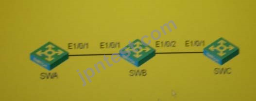
In the switching network as shown in the figure, all three switches have only default VLAN1. The interconnection ports of the three switches are Trunks, and all VLANs are allowed to pass. All three switches have the global and port GVRP functions enabled. VLAN 10 is created on the switch SWA, VLAN 20 is created on the switch SWC, and the GVRP registration mode of the Ethernet1/0/1 port is set to Forbidden on the switch SWA. Check the status of each Trunk port on the three switches. (Choose one or more)
正解:A、B
解答を投票する
The customer's two switches SWA and SWB are connected together through seven Ethernet cables and configured with dynamic link aggregation. The corresponding ports on the switch SWA are Ethernet 1/0/1, Ethernet 1/0/2, and Ethernet 1/0. /3, Ethernet 1/0/4, Ethernet 1/0/5, Ethernet 1/0/6, Ethernet 1/0/7o If the switches SWA and SWB only support 6 ports per aggregation group, and the SWA switch has the following Configuration:
[SWA]interface Ethernet 1/0/7
[SWA-Ethernet1/0/7]lacp port-priority 4096
Check LACP status on the device: output letter: as follows:
[SWA]display lacp system-id
Actor System ID: 0x8000, 00e1-fc00-5000
[SWB]display lacp system-id
Actor System ID: 0x8000, 00e0-fc43-7384
If you change SWA's LACP system priority to 4096, you can know from the above information
正解:A
解答を投票する
In the PIM-DM network as shown in the figure, part of the unicast routing table of routers RT1 and RT2 is as follows
<RT1>display ip routing-table
Routing Tables: Public
Destination/MaskProtoPreCost NextHop Interface
10.1.1.0/30 Direct 0010.1.1.2Port1
10.1.1.1/32 Direct 0010.1.1.1Port1
10.1.1.2/32 Direct 00127.0.0.1 InLoopO
11.1.1.0/30 Direct 0011.1.1.1Port2
11.1.1.1/32 Direct 00127.0.0.1 InLoopO
12.1.1.0/30 Direct 0012.1.1.1Port3
12.1.1.1/32 Direct 00127.0.0.1 InLoopO
100.1.1.0/240SPF 10 1563 10.1.1.1 Portl
127.0.0.0/8 Direct 00127.0.0.1 InLoopO
127.0.0.1/32Direct 00127.0.0.1 InLoopO
100.1.0.0/160SPF 10 311.1.1.2 Port2
<RT2>display ip routing-table
Routing Tables: Public
Destination/MaskProtoPreCost NextHop Interface
20.1.1.0/30 Direct 0020.1.1.2Port1
20.1.1.1/32 Direct 0020.1.1.1 Portl
20.1.1.2/32 Direct 00127.0.0.1 InLoopO
11.1.1.0/30 Direct 0011.1.1.2Port2
11.1.1.2/32 Direct 00127.0.0.1 InLoopO
22.1.1.0/30 Direct 0022.1.1.1Port3
22.1.1.1/32 Direct 00127.0.0.1 InLoopO
100.1.1.0/240SPF 10 1564 11.1.1.1 Port2
127.0.0.0/8 Direct 00127.0.0.1 InLoopO
127.0.0.1/32Direct 00127.0.0.1 InLoopO
100.1.0.0/160SPF 10 220.1.1.1 Portl
Then, the (S, G) entry and exit interface lists of routers RT1 and RT2 are respectively
正解:A、C
解答を投票する
In the networking shown in the figure, the PIM SM protocol runs between RT1, RT2, and RT3, the RP is 1.1.1.1 There is a multicast source connected to the downstream interface of RT1 and RT2, and there are downstream receivers on the RP, then when the RP sends After registering the stop message, which of the following routers have (S, G) entries

正解:A、B、C
解答を投票する
The two routers are connected through a LAN to form a VRRP backup group, and the configuration on each interface is as follows:
[RTA-GigabitEthernet1/0]display this
ip address 192.168.0.252 255.255.255.0
vrrp vrid 1 virtual-ip 192.168.0.254
[RTB-GigabitEthernet1/0]display this
ip address 192.168.0.253 255.255.255.0
vrrp vrid 1 virtual-ip 192.168.0.254
It can be known from the above information
[RTA-GigabitEthernet1/0]display this
ip address 192.168.0.252 255.255.255.0
vrrp vrid 1 virtual-ip 192.168.0.254
[RTB-GigabitEthernet1/0]display this
ip address 192.168.0.253 255.255.255.0
vrrp vrid 1 virtual-ip 192.168.0.254
It can be known from the above information
正解:D
解答を投票する
The ports Ethemet1/0/1, Ethernet1/0/2 and Ethernet1/0/3 of the switch SWA are Access, Trunk and Hybrid ports respectively, and the PVID is VLAN10. After executing the command undo vlan10 on SWA, check the configuration of each port Can you see which of the following-configuration
正解:C、F、G
解答を投票する

